

-
Welcome to Tacoma World!
You are currently viewing as a guest! To get full-access, you need to register for a FREE account.
As a registered member, you’ll be able to:- Participate in all Tacoma discussion topics
- Communicate privately with other Tacoma owners from around the world
- Post your own photos in our Members Gallery
- Access all special features of the site
 Rear Bumper Tire and Gas Can Carrier( please delete)
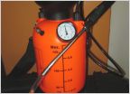 Garden Sprayer To Fluid Transfer Pump.....
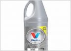 Diff fluid
 Toytec 5100 eibach coil overs and dakars w/AAL
 Operation: hit ‘em with the blue lights
 2nd gen Interior light
Want to change to LEDs and don't want to add resistors?
Discussion in '2nd Gen. Tacomas (2005-2015)' started by TRSAndrew, Apr 30, 2015.
Page 1 of 2
Page 1 of 2


