

-
Welcome to Tacoma World!
You are currently viewing as a guest! To get full-access, you need to register for a FREE account.
As a registered member, you’ll be able to:- Participate in all Tacoma discussion topics
- Communicate privately with other Tacoma owners from around the world
- Post your own photos in our Members Gallery
- Access all special features of the site
 Pop and Lock power tailgate lock questions
 5100 2 inch for 2012 DC.
 2TR-FE Head Gasket, Water Pump, etc
 Anyone experience with Dash Cams?
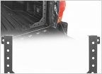 New player in the bed stiffener game...?
Toyota Tacoma V-6 1GR-FE valve clearance (lash) check and results
Discussion in '2nd Gen. Tacomas (2005-2015)' started by ah2006xrunner, Aug 13, 2023.


