

-
Welcome to Tacoma World!
You are currently viewing as a guest! To get full-access, you need to register for a FREE account.
As a registered member, you’ll be able to:- Participate in all Tacoma discussion topics
- Communicate privately with other Tacoma owners from around the world
- Post your own photos in our Members Gallery
- Access all special features of the site
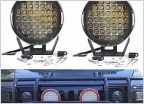 ARB Intensity knock offs
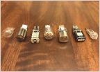 The 921 LED Reverse Light Bulb Study
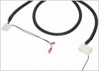 2013 4cyl Prerunnner w/ SR5
 LED lights interior/ backup/tag installed
 Need to Seal Open/Unused Fog Light Connectors?
 Interior LED bulb package
Rewiring the 4banger switch to an OEM alike
Discussion in 'Lighting' started by nircom, Jan 12, 2024.
Page 1 of 2
Page 1 of 2


