-
Welcome to Tacoma World!
You are currently viewing as a guest! To get full-access, you need to register for a FREE account.
As a registered member, you’ll be able to:- Participate in all Tacoma discussion topics
- Communicate privately with other Tacoma owners from around the world
- Post your own photos in our Members Gallery
- Access all special features of the site
 Walky talky?
 Straight Talk no BS on NAV/DVD/BT/Iphone hook up
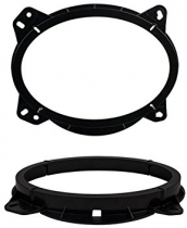
 What takeoffs will fit?
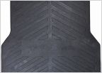 Information on toyota bed mats
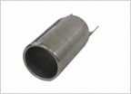 Trd exhaust tip
Normal for lift blocks to be angled?
Discussion in '2nd Gen. Tacomas (2005-2015)' started by Ts91, Sep 23, 2022.