

-
Welcome to Tacoma World!
You are currently viewing as a guest! To get full-access, you need to register for a FREE account.
As a registered member, you’ll be able to:- Participate in all Tacoma discussion topics
- Communicate privately with other Tacoma owners from around the world
- Post your own photos in our Members Gallery
- Access all special features of the site
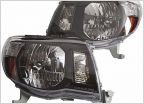 2nd Gen Retrofit Headlight suggestion
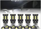 LED Lights
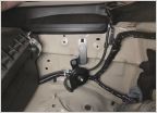 Fog Light Wiring Harness Info Needed
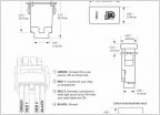 Wiring up CaliRaised LED's w/ OEM Switch
 Quick headlight question
 Switchback DRL/front directionals
Light Bar Switch Wiring Guide With Pictures! - Cali Raised & Air On Board Switches
Discussion in 'Lighting' started by BlackBeerd, Jun 29, 2019.


