

-
Welcome to Tacoma World!
You are currently viewing as a guest! To get full-access, you need to register for a FREE account.
As a registered member, you’ll be able to:- Participate in all Tacoma discussion topics
- Communicate privately with other Tacoma owners from around the world
- Post your own photos in our Members Gallery
- Access all special features of the site
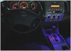 LED Interior Accent Lighting for '05-'11
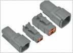 Preferred Connector type for added accessories
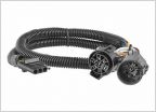 Hardwire Tailgate LED Bar
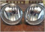 How To Remove 2005 - 2011 Fog Lights
 LED lights interior/ backup/tag installed
How to: Install light switch
Discussion in 'Lighting' started by Skoock, Aug 29, 2019.


