

-
Welcome to Tacoma World!
You are currently viewing as a guest! To get full-access, you need to register for a FREE account.
As a registered member, you’ll be able to:- Participate in all Tacoma discussion topics
- Communicate privately with other Tacoma owners from around the world
- Post your own photos in our Members Gallery
- Access all special features of the site
 Truck lost all electrical power
 Black TRD exhaust part #
 How do I remove cupholder chrome trim?
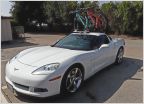 Any hitch mount bike rack recommendations?
 TPMS oem part number
 Someone drilled a hole in my gas tank
How can I add a second backup camera on my removable swingout on a 2020
Discussion in '3rd Gen. Tacomas (2016-2023)' started by StapleNut, Sep 25, 2021.
Page 5 of 5
Page 5 of 5


