

-
Welcome to Tacoma World!
You are currently viewing as a guest! To get full-access, you need to register for a FREE account.
As a registered member, you’ll be able to:- Participate in all Tacoma discussion topics
- Communicate privately with other Tacoma owners from around the world
- Post your own photos in our Members Gallery
- Access all special features of the site
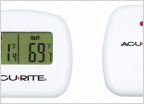 Help Needed: Adding an Outside Temp Display
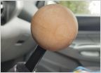 Made a custom wood shift knob: update
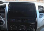 Adding Navigation to my 2012
 Removing a modular switch from the dash
 1gr Long Block Removal
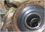 Tips on cleaning CV Axle seal mating surface
Having trouble with diode battery isolator
Discussion in '2nd Gen. Tacomas (2005-2015)' started by vanillion, Sep 9, 2013.


