-
Welcome to Tacoma World!
You are currently viewing as a guest! To get full-access, you need to register for a FREE account.
As a registered member, you’ll be able to:- Participate in all Tacoma discussion topics
- Communicate privately with other Tacoma owners from around the world
- Post your own photos in our Members Gallery
- Access all special features of the site
 EXHAUST: I WANT YOUR OPINION
 Cracked cylinder head cover?
 How to test coil pack
 Bidirectional scanner
 Very quick question re rear shocks
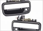 Door handle replacement help
Compustar CM900-AS Remote Start Install 2004 Toyota Tacoma
Discussion in '1st Gen. Tacomas (1995-2004)' started by Lehninger, Jan 1, 2024.