

-
Welcome to Tacoma World!
You are currently viewing as a guest! To get full-access, you need to register for a FREE account.
As a registered member, you’ll be able to:- Participate in all Tacoma discussion topics
- Communicate privately with other Tacoma owners from around the world
- Post your own photos in our Members Gallery
- Access all special features of the site
 Has anyone with a boat tried this dual-use trailer hitch?
 Will this work on Tacoma Sr
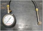 Tire Air Pressure Gauge
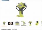 Recommendations for portable tire inflator
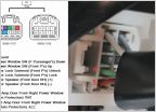 Tailgate power lock
 Exterior door handle protection
Building a 8020 roofrack?
Discussion in '3rd Gen. Tacomas (2016-2023)' started by dschreib, Sep 10, 2019.


