

-
Welcome to Tacoma World!
You are currently viewing as a guest! To get full-access, you need to register for a FREE account.
As a registered member, you’ll be able to:- Participate in all Tacoma discussion topics
- Communicate privately with other Tacoma owners from around the world
- Post your own photos in our Members Gallery
- Access all special features of the site
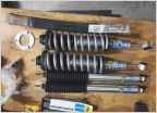 3" Bilstein 5100/Toytec AAL Suspension lift Guide
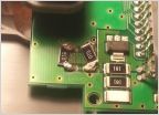 05 Compass, Temp circut board
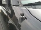 Antenna
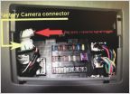 Backup camera output to aftermarket radio
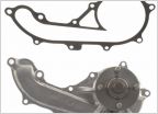 Do it myself or have local mechanic or dealership replace water pump
Blower Motor Resistor Fix: PWM
Discussion in '2nd Gen. Tacomas (2005-2015)' started by purekentucky, Mar 2, 2019.
Page 1 of 2
Page 1 of 2


