

-
Welcome to Tacoma World!
You are currently viewing as a guest! To get full-access, you need to register for a FREE account.
As a registered member, you’ll be able to:- Participate in all Tacoma discussion topics
- Communicate privately with other Tacoma owners from around the world
- Post your own photos in our Members Gallery
- Access all special features of the site
 How to repair broken headlight tab (not a Tacoma)
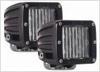 LED PODS SPOTS OR FLOODS?
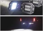 Other uses for flush mount LED pods
 Floorboard lights on with dome light?
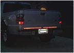 Got Reflective Tape?
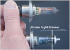 Best Headlight Replacement Bulb?
5 pin rocker switch help.......
Discussion in 'Lighting' started by CountryDan, Jun 30, 2016.


